Technical article ·
Designing Smart Batteries into Medical Devices

From the archive. Published May 2003. Part numbers, specifications and availability are as they were then. For what we build today, see the product catalog.
Portable electronic devices are penetrating the medical industry at an ever-increasing rate. At the core of all these devices are the batteries that power them and the success of the device rests heavily on a successful battery design. In the case of many medical devices, the accuracy & reliability of the fuel gauging system is crucial, and a battery with built-in intelligence (Smart Battery) may be required. Early consultation with your smart battery designer should yield designs with reduced component counts & lower cost assembly. Hence close attention to the smart battery design right from the outset can result in savings in the final product.
Choosing the correct cell chemistry & size is the first major choice facing the battery designer. Typical drivers are size, weight, cost, power delivery, form factor and environmental considerations, and these researches may send you back to the drawing board a few times - smart battery design is an iterative process, exploring a variety of alternatives. A common request is for a specific nominal operating voltage. However in battery powered devices the critical voltage is the cutoff, not the nominal voltage. All cell technologies have sloping voltage curves & hence battery packs must be designed so that their cutoff point is compatible with that of the device.
A basic application using a couple of NiCd cells, is unlikely to need in-pack electronics, and an application like a cellphone has no real penalty if the fuel gauge is inaccurate - the worst that can happen is that a call is cut short. However any application that relies on the battery functioning exactly as predicted by its fuel gauge needs a more sophisticated monitoring & gauging system.
Lithium cells are rapidly becoming the main power source for portable electronic devices, & the increasing sophistication of the devices calls for an increased level of communication of key battery performance parameters to the user. Aside from cell protection, and fuel gauging, a common requirement is battery-to-device communications. This capability enables the battery to communicate critical data directly to the host device &/or the user. It is much more than an LED display on the battery, smart batteries can communicate detailed diagnostic data, thermal information, cycle history, and can carry out complex functions such as using the recent discharge history to calculate & provide a “remaining time to empty”.
Unlike automobiles, the “fuel tank” on a battery pack shrinks & grows as the battery ages and with changing temperature and rate of discharge. Also the accuracy of the digital fuel gauge can drift if the battery is used in applications of frequent partial discharges. In order to provide, accurate, precise fuel gauging, these conditions require a sophisticated fuel gauge with extremely high resolution & the ability to “learn” & recalibrate in order to provide the user with dependable information.
The implementation of electronics increases the costs of samples & pre-production units. Small PCB runs involve tooling charges, but are a vital part of new product introduction. Although it represents an early expense, this design process is the single most critical factor in the success of the project. Over the project life, the cost of the design will be greatly outweighed by the costs of materials, burden & labor, yet the effects of that design will continue to affect the project cost throughout its life. Figure 1 demonstrates how the design & pre-production phases can significantly affect the profitability of the overall project.
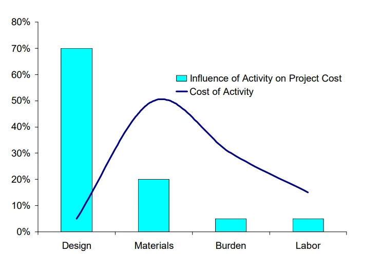
The use of in-pack electronics will also result in higher levels of product testing, first at the populated PCB level & later, confirmation of the electronic function & the interface between battery & device. Frequently this testing requires sophisticated electronic test equipment & requires close attention. In high volume manufacture, residence time in electronics test must be carefully weighed against the cost of test units to match the line throughput.
The time to develop an integrated intelligent battery pack design should be less than that required for the host device. The key is to start this process as early as possible & run the battery & device designs along parallel paths. The 4-phase development model outlined below is an effective way to manage smart battery product development. Each phase includes a review by both customer and suppliers, to ensure that the scope, quality, timing, feasibility & costs, etc. are still on course. This process check allows all parties to review the project & appropriate action can be taken at each stage gate to ensure the project remains on track.
Fig 2 – Four-Phase Smart Battery Development Process
Phase I - Engineering Feasibility
- Typically 2-20 pieces built in a laboratory using prototype cases & circuit boards
- Samples approved by safety and applications team prior to issuing to the client
- Emphasis is on rapid prototyping techniques, in close cooperation with the client
- Critical needs are identified and recorded
- Minimal documentation created & archived, but not released
- May involve tooling, NRE, production budgetary
- Timing can vary from a few days to a few months depending on the design complexity
- Goal is a first look at fundamental feasibility, under a controlled environment
Stage Gate: customer review & approval of prototypes
Phase II - Design Confirmation Run
- Typically 20-100 pieces built in a laboratory with manufacturing engineering attendance
- Incorporates modifications highlighted by Phase 1 in statistically larger build
- Corresponds to the device moving from alpha to beta development stage
- Uses rapid prototype components, but employs production-type cycling & end-of line tests
- Creation of version 0.1 of specification & test requirements documentation
- Initial assessment of assembly line fixturing & equipment needs
Stage Gate: customer review & approval of design. Ordering of production tooling for plastics, boards & test equipment
Phase III - Production Pilot Run
- Typically 100-300 pieces built on manufacturing shop floor to prove-in fixtures, testing, & process lay-out
- Intensive data collection at incoming, in process, final line
- AQL audit conducted on finished goods
- Bill of material & drawing packages are finalized, & part numbers assigned
Stage Gate: Customer review of pilot run & release of design for manufacturing
Phase IV - Manufacturing Prove-in
- Typically 3 months of continuous production on manufacturing shop floor
- Continuous improvement & process refinement begins
- Final refinements to documentation, process and procedures
- Release of rev 1.0 specification
- Assessment of cost-reduction opportunities begins
Using this type of phased approach, battery product development provides working products in a timely and cost-effective manner.
Designing a smart power source for your portable electronic device is a complex assignment, the success of which is directly proportional to the amount of time & effort spent at the design stage. Early involvement with an experienced smart battery designer will result in the optimum choices in technology, electronics and battery design. This will ensure that your product has the best possible chance of success.